Architect / Designer
Control grid scale, transparency, moiré risk, orientation and continuity across the elevation.

A cable-and-rod mesh with a clear rectangular rhythm for large architectural surfaces where visual openness, directional flexibility and support engineering must work together.
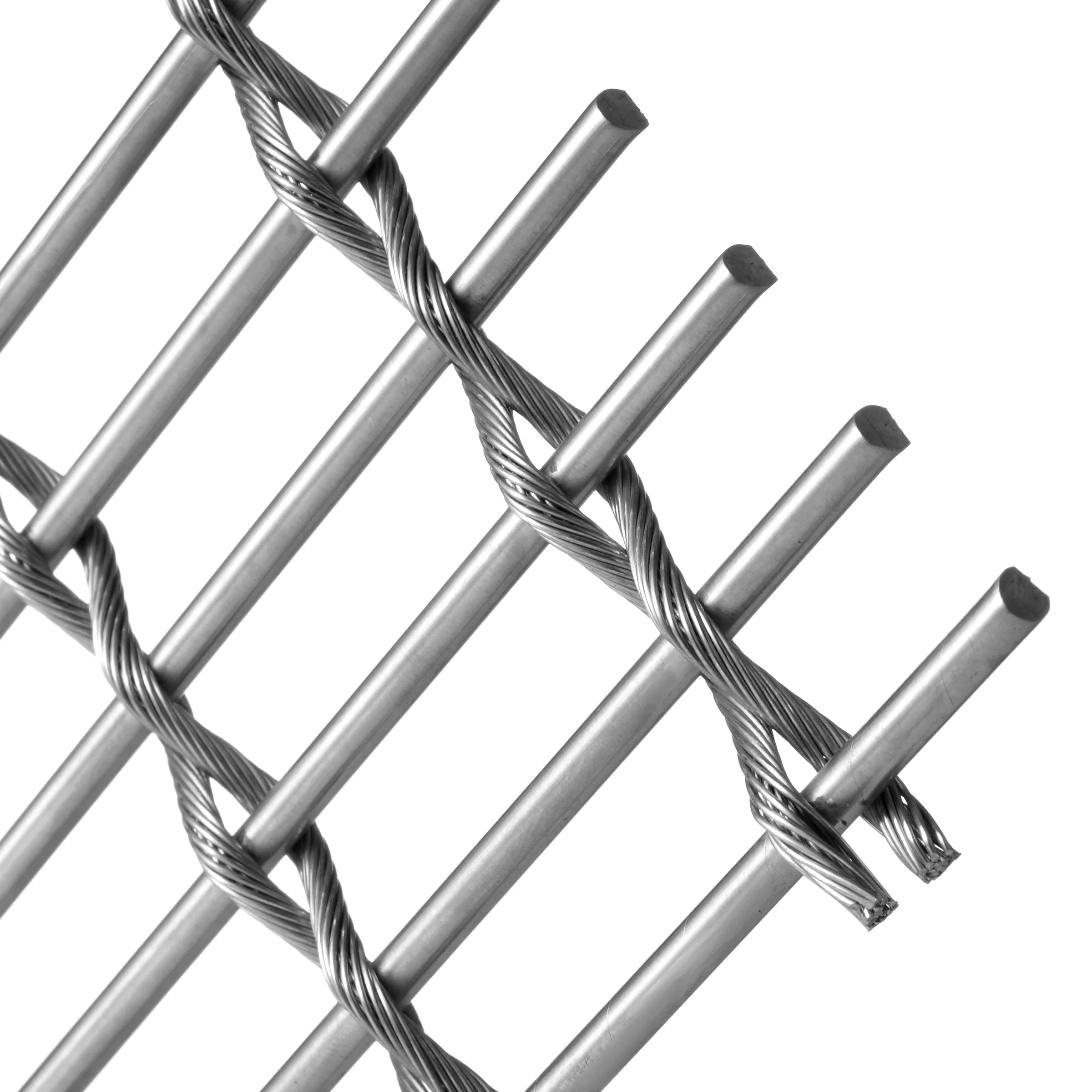
JA-F001 should be selected by elevation scale and interface conditions. The mesh is only one part of the result; cable direction, rod direction, support spacing, tension, panel breaks and edge hardware determine whether the installed surface remains controlled.
Stainless-steel cable elements run in one direction and rigid rods cross them in the other, creating a flexible sheet with a strong linear grid. Its behaviour differs by direction and must be coordinated with the proposed suspension or frame.
Mesh orientation on the elevation
Allowable panel width and panel breaks
Top load path and lower restraint
Edge cable, clevis, frame or custom connection
Wind, access and maintenance conditions
Alignment of grid across adjacent panels
Control grid scale, transparency, moiré risk, orientation and continuity across the elevation.
Define loads, support centres, deflection limits, edge restraint and coordination with the primary structure.
Confirm panel schedule, hardware responsibility, approved sample and packing sequence before release.
These values identify the recorded reference configuration. They are not a substitute for the approved quotation, sample, drawing and order specification.
Dimensioned elevation and panel schedule
Mesh orientation
Primary structure and fixing zones
Design loads and site exposure
Required edge and tensioning concept
Finish and sample approval requirement
Cable and rod spacing
Surface flatness under proposed tension
Edge termination
Grid alignment between panels
Finish consistency and handling marks
After the model, configuration, finish, edges, dimensions and responsibilities are approved, the order record carries those requirements into production planning, inspection, packing and delivery coordination.
The listed values come from the enterprise technical sheet and describe a reference configuration. Final material, dimensions, finish, edges, interfaces and order scope must be confirmed against the current project.
Send dimensioned drawings, application, panel schedule, supporting construction, edge or fixing intent, finish requirement, site conditions and the required approval date.
A sample confirms the actual weave, scale, colour, reflection, edge workmanship and handling expectation. For framed or tensioned work, a representative assembly or mock-up may be needed.
We will review product fit, missing project inputs, sample requirements and the path to an order-ready specification.